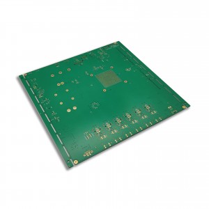
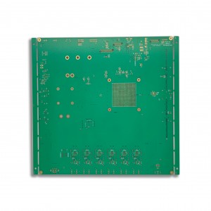
Papan Sirkuit PCB 4 Lapis dengan BGA untuk Peralatan Semikonduktor
Info dasar
| Model nomor. | PCB-A49 |
| Paket transportasi | Pengepakan Vakum |
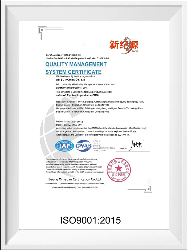
| Sertifikasi | UL,ISO9001&ISO14001,RoHS |
| Aplikasi | Elektronik konsumen |
| Spasi/Garis Minimal | 0,075mm/3mil |
| Kapasitas produksi | 50.000 meter persegi/bulan |
| Kode HS | 853400900 |
| Asal | Buatan China |
Deskripsi Produk
Pengenalan PCB FR4
FR berarti “tahan api,” FR-4 (atau FR4) adalah sebutan kelas NEMA untuk bahan laminasi epoksi yang diperkuat kaca, bahan komposit yang terdiri dari kain tenun fiberglass dengan pengikat resin epoksi yang menjadikannya substrat ideal untuk komponen elektronik pada papan sirkuit tercetak.

Pro dan Kontra PCB FR4
Bahan FR-4 sangat populer karena kualitasnya yang luar biasa yang dapat bermanfaat bagi papan sirkuit cetak.Selain terjangkau dan mudah digunakan, ini merupakan isolator listrik dengan kekuatan dielektrik yang sangat tinggi.Selain itu, tahan lama, tahan lembab, tahan suhu, dan ringan.
FR-4 adalah material yang sangat relevan, populer terutama karena biayanya yang rendah dan stabilitas mekanik dan listrik yang relatif.Meskipun bahan ini memiliki banyak manfaat dan tersedia dalam berbagai ketebalan dan ukuran, bahan ini bukanlah pilihan terbaik untuk setiap aplikasi, terutama aplikasi frekuensi tinggi seperti desain RF dan gelombang mikro.
Struktur PCB multi-lapisan
PCB multilapis semakin meningkatkan kompleksitas dan kepadatan desain PCB dengan menambahkan lapisan tambahan di luar lapisan atas dan bawah yang terlihat pada papan dua sisi.PCB multilayer dibuat dengan melaminasi berbagai lapisan.Lapisan dalam, biasanya papan sirkuit dua sisi, ditumpuk bersama-sama, dengan lapisan isolasi di antara dan di antara foil tembaga untuk lapisan luar.Lubang yang dibor melalui papan (vias) akan membuat sambungan dengan berbagai lapisan papan.
Teknis & Kemampuan
Papan Sirkuit Papan PCB dengan Sertifikat UL, SGS, ISO
PCB Tunggal, Sisi Ganda & Multi-lapis
Vias Terkubur/Blind, Via in Pad, Lubang Counter Sink, Lubang Sekrup (Counterbore), Press-fit, Setengah Lubang
HASL bebas timah, Perendaman Emas/ Perak/Timah, OSP, Pelapisan emas/jari, Masker yang dapat dikupas
Papan Sirkuit Cetak mematuhi standar PCB internasional IPC Kelas 2 & 3
Jumlahnya berkisar dari prototipe hingga produksi batch menengah & besar
100% E-Tes
| Barang | Kapasitas produksi |
| Jumlah Lapisan | 1-32 |
| Bahan | FR-4, TG Tinggi FR-4, PTFE, Basis Aluminium, Basis Cu, Rogers, Teflon, dll |
| Ukuran maksimum | 600mm X1200mm |
| Toleransi Garis Besar Dewan | ±0,13mm |
| Ketebalan Papan | 0,20mm–8,00mm |
| Toleransi Ketebalan (t≥0.8mm) | ±10% |
| Toleransi Ketebalan (t<0,8mm) | ±0,1mm |
| Ketebalan Lapisan Isolasi | 0,075mm–5,00mm |
| Minimal itu | 0,075mm |
| Ruang Minimal | 0,075mm |
| Ketebalan Tembaga Lapisan Luar | 18um–350um |
| Ketebalan Tembaga Lapisan Dalam | 17um–175um |
| Lubang Pengeboran (Mekanis) | 0,15mm–6,35mm |
| Lubang Selesai (Mekanis) | 0,10mm–6,30mm |
| Toleransi Diameter (Mekanis) | 0,05mm |
| Registrasi (Mekanis) | 0,075mm |
| Rasio Aspek | 16:01 |
| Jenis Masker Solder | LPI |
| Lebar Masker SMT Mini.Solder | 0,075mm |
| Izin Masker Mini.Solder | 0,05mm |
| Diameter Lubang Steker | 0,25mm–0,60mm |
| Toleransi Kontrol Impedansi | 10% |
| Permukaan Selesai | HASL/HASL-LF, ENIG, Timah Perendaman/Perak, Emas Flash, OSP, Jari Emas, Emas Keras |

Dari mana asal bahan resin di ABIS?
Kebanyakan dari mereka berasal dari Shengyi Technology Co., Ltd. (SYTECH), yang telah menjadi produsen CCL terbesar kedua di dunia dalam hal volume penjualan, dari tahun 2013 hingga 2017. Kami menjalin hubungan kerja sama jangka panjang sejak tahun 2006. Bahan resin FR4 (Model S1000-2, S1141, S1165, S1600) terutama digunakan untuk membuat papan sirkuit cetak satu dan dua sisi serta papan multi-lapis.Inilah detailnya untuk referensi Anda.
Untuk FR-4: Sheng Yi, King Board, Nan Ya, Polycard, ITEQ, ISOLA
Untuk CEM-1 & CEM 3: Sheng Yi, Dewan Raja
Untuk Frekuensi Tinggi : Sheng Yi
Untuk Penyembuhan UV: Tamura, Chang Xing ( * Warna yang tersedia : Hijau) Solder untuk Satu Sisi
Untuk Foto Cair: Tao Yang, Resist (Film Basah)
Chuan Yu ( * Tersediawarna: Putih, Bisa Dibayangkan Solder Kuning, Ungu, Merah, Biru, Hijau, Hitam)
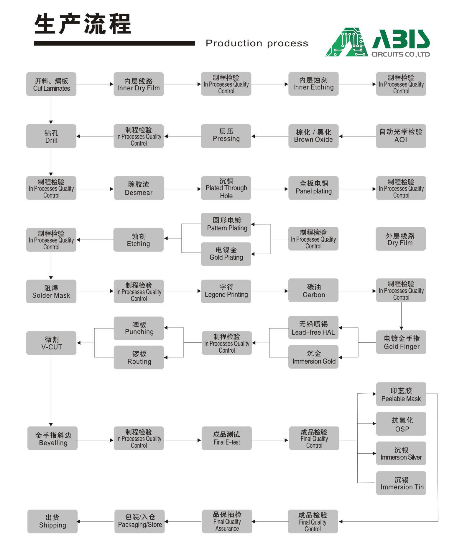
Proses Produksi PCB
Prosesnya dimulai dengan merancang Tata Letak PCB menggunakan perangkat lunak perancang PCB / Alat CAD (Proteus, Eagle, Atau CAD).
Semua langkah selanjutnya adalah Proses Pembuatan Papan Sirkuit Cetak Kaku sama dengan PCB Satu Sisi atau PCB Dua Sisi atau PCB Multi-lapis.
Waktu Pimpin Q/T
| Kategori | Waktu Pimpin Tercepat | Waktu Pimpin Biasa |
| Dua sisi | 24 jam | 120 jam |
| 4 Lapisan | 48 jam | 172 jam |
| 6 Lapisan | 72 jam | 192 jam |
| 8 Lapisan | 96 jam | 212 jam |
| 10 Lapisan | 120 jam | 268 jam |
| 12 Lapisan | 120 jam | 280 jam |
| 14 Lapisan | 144 jam | 292 jam |
| 16-20 Lapisan | Tergantung pada persyaratan spesifik | |
| Di atas 20 Lapisan | Tergantung pada persyaratan spesifik | |
Langkah ABIS untuk mengendalikan FR4 PCBS
Persiapan Lubang
Menghilangkan serpihan dengan hati-hati & menyesuaikan parameter mesin bor: sebelum melapisi dengan tembaga, ABIS memberikan perhatian tinggi pada semua lubang pada PCB FR4 yang dirawat untuk menghilangkan serpihan, ketidakteraturan permukaan, dan noda epoksi, lubang yang bersih memastikan pelapisan berhasil menempel pada dinding lubang .juga, di awal proses, parameter mesin bor disesuaikan secara akurat.
Persiapan Permukaan
Melakukan deburring dengan hati-hati: pekerja teknologi kami yang berpengalaman akan menyadari sebelumnya bahwa satu-satunya cara untuk menghindari hasil yang buruk adalah dengan mengantisipasi perlunya penanganan khusus dan mengambil langkah-langkah yang tepat untuk memastikan bahwa proses tersebut dilakukan dengan hati-hati dan benar.
Tingkat Ekspansi Termal
Terbiasa menangani berbagai material, ABIS akan mampu menganalisa kombinasi tersebut untuk memastikan kesesuaiannya.kemudian menjaga keandalan CTE (koefisien ekspansi termal) dalam jangka panjang, dengan CTE yang lebih rendah, semakin kecil kemungkinan kegagalan pelapisan melalui pelenturan tembaga berulang kali yang membentuk interkoneksi lapisan internal.
Penskalaan
Kontrol ABIS pada sirkuit ditingkatkan dengan persentase yang diketahui untuk mengantisipasi kerugian ini sehingga lapisan akan kembali ke dimensi yang dirancang setelah siklus laminasi selesai.juga, dengan menggunakan rekomendasi penskalaan dasar dari produsen laminasi yang dikombinasikan dengan data kontrol proses statistik internal, untuk menentukan faktor skala yang akan konsisten dari waktu ke waktu dalam lingkungan manufaktur tertentu.
permesinan
Ketika tiba saatnya untuk membuat PCB Anda, ABIS pastikan bahwa Anda memilih memiliki peralatan dan pengalaman yang tepat untuk memproduksinya dengan benar pada percobaan pertama.
Misi Mutu ABIS
Tingkat kelulusan material yang masuk di atas 99,9%, jumlah tingkat penolakan massal di bawah 0,01%.
Fasilitas bersertifikasi ABIS mengendalikan semua proses utama untuk menghilangkan semua potensi masalah sebelum produksi.
ABIS menggunakan perangkat lunak canggih untuk melakukan analisis DFM ekstensif pada data yang masuk, dan menggunakan sistem kendali mutu canggih di seluruh proses produksi.
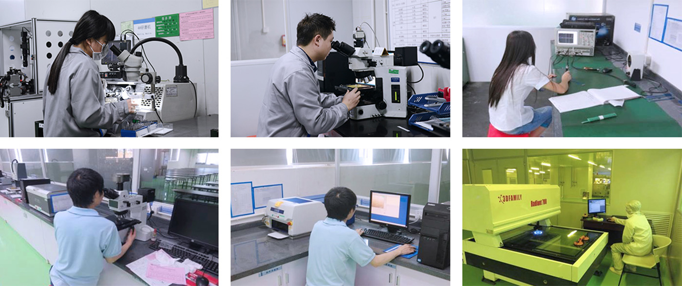
ABIS melakukan inspeksi visual dan AOI 100% serta melakukan pengujian kelistrikan, pengujian tegangan tinggi, pengujian kontrol impedansi, pemotongan mikro, pengujian kejutan termal, pengujian solder, pengujian keandalan, pengujian resistansi isolasi, dan pengujian kebersihan ionik.

Sertifikat
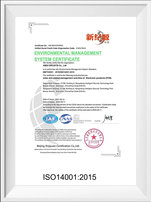
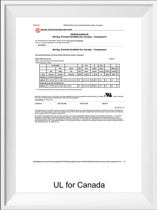
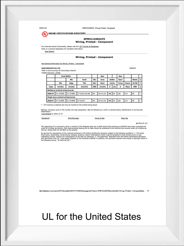
Apa kelebihan manufaktur di ABIS?
Lihatlah sekelilingmu.Banyak sekali produk yang berasal dari Tiongkok.Tentu saja hal ini mempunyai beberapa alasan.Ini bukan lagi hanya soal harga.
Mempersiapkan kutipan dilakukan dengan cepat.
Pesanan produksi selesai dengan cepat.Anda dapat merencanakan pesanan yang dijadwalkan berbulan-bulan sebelumnya, kami dapat mengaturnya segera setelah PO dikonfirmasi.
Rantai pasokan berkembang pesat.Itu sebabnya kami dapat membeli setiap komponen dari mitra khusus dengan sangat cepat.
Karyawan yang fleksibel dan bersemangat.Oleh karena itu, kami menerima setiap pesanan.
Layanan online 24 jam untuk kebutuhan mendesak.Jam kerja +10 jam per hari.
Biaya lebih rendah.Tidak ada biaya tersembunyi.Menghemat personel, overhead, dan logistik.
Pertanyaan Umum
Untuk memastikan penawaran harga yang akurat, pastikan untuk menyertakan informasi berikut untuk proyek Anda:
Lengkapi file GERBER termasuk daftar BOM
l Kuantitas
l Putar waktu
l Persyaratan Panelisasi
l Persyaratan Bahan
l Selesaikan persyaratan
l Penawaran khusus Anda akan dikirimkan hanya dalam 2-24 jam, tergantung kerumitan desain.
Diperiksa dalam waktu 12 jam.Setelah pertanyaan Insinyur dan file kerja diperiksa, kami akan memulai produksi.
Prosedur Penjaminan Mutu kami seperti di bawah ini:
a), Inspeksi Visual
b), Probe terbang, alat perlengkapan
c), Kontrol impedansi
d), deteksi kemampuan solder
e), Mikroskop metalografi digital
f),AOI (Inspeksi Optik Otomatis)
Ya, kami dengan senang hati menyediakan sampel modul untuk menguji dan memeriksa kualitas, pesanan sampel campuran tersedia.Harap dicatat pembeli harus membayar biaya pengiriman.
Tingkat pengiriman tepat waktu lebih dari 95%
a), putaran cepat 24 jam untuk prototipe PCB sisi ganda
b),48 jam untuk prototipe PCB 4-8 lapis
c),1 jam untuk kutipan
d),2 jam untuk pertanyaan insinyur/umpan balik Keluhan
e),7-24 jam untuk dukungan teknis/layanan pemesanan/operasi manufaktur
ABlS melakukan inspeksi visual dan AOl 100% serta melakukan pengujian kelistrikan, pengujian tegangan tinggi, pengujian kontrol impedansi, pemotongan mikro, pengujian kejutan termal, pengujian solder, pengujian keandalan, pengujian resistansi isolasi, pengujian kebersihan ionik, dan pengujian Fungsional PCBA.
a), kutipan 1 jam
b),2 jam umpan balik keluhan
c), dukungan teknis 7*24 jam
d), layanan pemesanan 7*24
e), pengiriman 7*24 jam
f),7*24 produksi dijalankan
Industri Utama ABIS: Pengendalian Industri, Telekomunikasi, Produk Otomotif dan Medis.Pasar Utama ABIS: 90% Pasar Internasional (40%-50% untuk AS, 35% untuk Eropa, 5% untuk Rusia dan 5%-10% untuk Asia Timur) dan 10% Pasar Domestik.
·Dengan ABIS, pelanggan mengurangi biaya pengadaan global mereka secara signifikan dan efektif.Di balik setiap layanan yang diberikan ABIS, tersembunyi penghematan biaya bagi pelanggan.
.Kami memiliki dua toko bersama, satu untuk prototipe, perputaran cepat, dan pembuatan volume kecil.Kedua, untuk produksi massal juga untuk pengurus HDI, dengan karyawan profesional berketerampilan tinggi, untuk produk berkualitas tinggi dengan harga bersaing dan pengiriman tepat waktu.
.Kami memberikan dukungan penjualan, teknis dan logistik yang sangat profesional, di seluruh dunia dengan umpan balik keluhan 24 jam.


